OP AMP
About[]
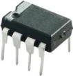
The operational amplifier , often referred to informally as an op amp, is a circuit that provides extremely high-gain amplification of the difference in voltage between two inputs. One input is known as the inverting input (' - ' symbol) and the other is known as the non-inverting input (' + ' symbol). There is only a single output. The input impedance of the inverting and non-inverting inputs is extremely high. The output impedance of the op amp is very low. Modern op amps are integrated circuits. Not shown in this symbol are connections for the power supplies. Omitting them from schematic drawings is customary, although in practice they must be connected. Op amps are available with bipolar or unipolar power supplies. [1][2]
Simplified Behavior[]
The simplest model describing the behavior of an op amp relates its output to a multiple of the difference between the voltage at its non-inverting input and the voltage at its inverting input: . Manufacturing processes make it difficult to obtain a specified value of the multiple , and this multiplier is, in fact, not a constant but a function of frequency. However, for low frequencies is very large. This leads to some interesting consequences, as we shall see.


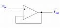
The standard symbol for an op amp is shown below:
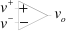
OP AMP Symbol. ' - ' symbol is inverting input and ' + ' is noninverting input
Inverting Amplifier[]
In this section we analyze a circuit with the configuration shown below:
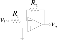
Inverting OP AMP. ' - ' symbol is inverting input and ' + ' is noninverting input
We analyze it twice, first using the expression , an expression that we regard as modeling a so-called non-ideal op amp. Once we have done this and understand how this op amp configuration behaves, we will analyze the circuit again using a simpler approach, using so-called ideal op amps.
The formula for gain is:

Non-ideal Op Amps[]
We can develop two equations relating the output voltage to the input voltage . The first of these can be found by using superposition:


The second is the equation describing the basic behavior of the op amp:

Noting that and solving the second of these equations for gives


Now we can substitute this into the first of our two equations:

Subtracting from both sides and factoring out on the left hand side yields


Dividing boths sides by and by yields the gain


This can be rewritten more simply if both numerator and denominator are multiplied by :


Now if is very large, the first term in the denominator can be neglected and the gain is

This shows that the amplification constant of the op amp vanishes from the overall expression for the gain because it is very large. The gain of the circuit is instead determined solely by the external components. This means that the high variability of in manufacture does not affect the behavior of the circuit in which the op amp is embedded. As long as is sufficiently large, the approximation is reasonable.
The configuration we have analyzed here is that of an inverting amplifier. It is inverting because of the negative sign. The magnitude of the gain is determined by the ratio of and can be either greater than or less than one.

Ideal Op Amps[]
Analysis of circuits with op amps in them can be simplified by assuming two idealizations of an op amp's behavior:
- The currents entering the inverting and non-inverting terminals of the op amp are zero.

A consequence of the first of these idealizations is that the voltages at both input terminals must be equal:

In the circuit analyzed above, this means that because is grounded.

Of course, in reality and cannot be precisely equal, for if they were, the output of the amplifier would be zero. However, because is very large, the difference is very small and we assume it can be neglected.
Using the idealized behavior lets us calculate the current flowing through from left to right very simply as


The second of the two idealizations means that all this current flows through . None of it can flow into the inverting terminal of the op amp. We achieve the same result, but using the idealized model of an op amp permits us to do so with substantially less analysis. In general, assuming that an op amp behaves in this ideal manner makes it easy to get a rough idea of how a circuit will behave.

Later on we will see that the dependence of on frequency will require us to investigate the behavior of our circuit more carefully when the inputs contain higher frequencies.
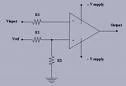
Non-inverting Amplifier[]
Consider next this circuit:
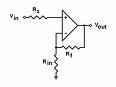
Noninverting OP AMP. ' - ' symbol is inverting input and ' + ' is noninverting input
Using the idealized op amp assumptions, we see that

This means that current flowing from right to left through is

and all of this current must also flow from right to left through since the op amp takes in no current at its input terminals. In this configuration the gain is positive and at least as great as one. This configuration provides a non-inverting amplifier.
The formula for gain is:

Voltage Follower (Current Buffer)[]
The op amp in this configuration:
Voltage Follower OP AMP
is identical to the non-inverting amplifier configuration if we pick and . The output or gain formula, therefore, is


Because the ideal op amp draws no current from the source and because it has very low output impedance, this circuit provides a replica of the input without loading the circuit that provides the input voltage. Many sensors, such as some microphones, have a high output impedance. Drawing current from them would result in a reduction of the voltage sensed by the amplifier. This circuit prevents that, leading to the alternate name current buffer for this circuit.
Output Impedance[]
Up to this point we have tacitly treated the output impedance of an op amp as zero. The output impedance of a typical op amp, such as the LM741, is around 75 Ω. A more suitable model of an op amp treats it as a voltage-controlled voltage source with an output resistance .

To calculate the output impedance of a circuit such as the inverting amplifier configuration, suppress the input voltage, apply a test voltage to the output, and calculate the output current. Taking the ratio of test voltage divided by output current gives the output resistance.
Since negligible current enters the op amp at its inverting terminal, we can calculate the current flowing from right to left through as

For sufficiently large values of the third term in the denominator dominates the first two, forcing to become much smaller than , the output resistance of the op amp itself.

Notice that the same analysis applies to the non-inverting configuration because, when the input voltages are suppressed, it is indistinguishable from the inverting amplifier just analyzed.
This analysis shows that one of the great benefits of using op amps with large gain is that they make it possible to build circuits with very small output impedance. This means that when connected as a source to other circuit elements, there is a negligible signal loss at the next stage's input.
Practical Usage[]
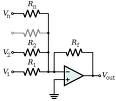
Summing Amplifier[]
Summin OP AMP
The summing amplifier is a handy circuit enabling you to add several signals together. What are some examples? If you're measuring temperature, you can add a negative offset to make the display read "0" at the freezing point. On a precision amplifier, you may need to add a small voltage to cancel the offset error of the op amp itself. An audio mixer is another good example of adding waveforms (sounds) from different channels (vocals, instruments) together before sending the combined signal to a recorder.
Although, there are many ways to make a summer, this one is nice because it keeps the interaction between inputs at a minimum. What does that mean for you the designer? You can change the gain or add another input without messing with the gains of the other inputs. Just remember that the circuit also inverts the input signals. Not a big deal. If you need the opposite polarity, put an inverting stage before or after the summer.
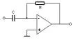
Differentiators[]
Differentiator OP AMP
The differentiator (not to be confused with differential) produces a voltage output proportional to the input voltage's rate of change. The right-hand side of the capacitor is held to a voltage of 0 volts, due to the "virtual ground" effect. Therefore, current "through" the capacitor is solely due to change in the input voltage. A steady input voltage won't cause a current through C, but a changing input voltage will.
Capacitor current moves through the feedback resistor, producing a drop across it, which is the same as the output voltage. A linear, positive rate of input voltage change will result in a steady negative voltage at the output of the op-amp. Conversely, a linear, negative rate of input voltage change will result in a steady positive voltage at the output of the op-amp. This polarity inversion from input to output is due to the fact that the input signal is being sent (essentially) to the inverting input of the op-amp, so it acts like the inverting amplifier mentioned previously. The faster the rate of voltage change at the input (either positive or negative), the greater the voltage at the output.
Applications for this, besides representing the derivative calculus function inside of an analog computer, include rate-of-change indicators for process instrumentation. One such rate-of-change signal application might be for monitoring (or controlling) the rate of temperature change in a furnace, where too high or too low of a temperature rise rate could be detrimental. The DC voltage produced by the differentiator circuit could be used to drive a comparator, which would signal an alarm or activate a control if the rate of change exceeded a pre-set level.
In process control, the derivative function is used to make control decisions for maintaining a process at setpoint, by monitoring the rate of process change over time and taking action to prevent excessive rates of change, which can lead to an unstable condition. Analog electronic controllers use variations of this circuitry to perform the derivative function.
On the other hand, there are applications where we need precisely the opposite function, called integration in calculus. Here, the op-amp circuit would generate an output voltage proportional to the magnitude and duration that an input voltage signal has deviated from 0 volts. Stated differently, a constant input signal would generate a certain rate of change in the output voltage: differentiation in reverse.
Basically, a differentiator circuit produces a constant output voltage for a steadily changing input voltage.
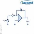
Integrator[]
Integrator OP AMP
The integrator produces a voltage output proportional to the product (multiplication) of the input voltage and time. As before, the negative feedback of the op-amp ensures that the inverting input will be held at 0 volts (the virtual ground). If the input voltage is exactly 0 volts, there will be no current through the resistor, therefore no charging of the capacitor, and therefore the output voltage will not change. We cannot guarantee what voltage will be at the output with respect to ground in this condition, but we can say that the output voltage will be constant.
However, if we apply a constant, positive voltage to the input, the op-amp output will fall negative at a linear rate, in an attempt to produce the changing voltage across the capacitor necessary to maintain the current established by the voltage difference across the resistor. Conversely, a constant, negative voltage at the input results in a linear, rising (positive) voltage at the output. The output voltage rate-of-change will be proportional to the value of the input voltage.
One application for this device would be to keep a "running total" of radiation exposure, or dosage, if the input voltage was a proportional signal supplied by an electronic radiation detector. Nuclear radiation can be just as damaging at low intensities for long periods of time as it is at high intensities for short periods of time. An integrator circuit would take both the intensity (input voltage magnitude) and time into account, generating an output voltage representing total radiation dosage.
Another application would be to integrate a signal representing water flow, producing a signal representing total quantity of water that has passed by the flowmeter. This application of an integrator is sometimes called a totalizer in the industrial instrumentation trade.
Basically, an integrator circuit produces a steadily changing output voltage for a constant input voltage.
Comparator[]
The amplification of the operational amplifier depends purely upon the ratio of a feedback resistor to the input resistor. And now, let us assume that the feedback resistor is missing, and the input is connected directly to the op amp IC without and input resistors.
Comparator OP AMP
If the input resistor is missing, the gain loop is open. In another word we can say that the Feedback Resistance is infinitely high, and the gain of the operational amplifier is infinitely high. However, what does determine the sign (+/-) of the gain. This is the difference between negative and positive inputs.
- In non-inverting amplifier circuit the inverting input is grounded (through resistors), and the input goes to positive.
- In the inverting amplifier circuit, the non-inverting input is grounded, and the input goes to the inverting input.
- In both cases the voltage on the non-in-use input is close to ZERO. Therefore the incoming signal is absolute.
In comparator, a reference voltage is supplied to the positive input, and the negative input measures the input voltage. The reference voltage is obtained by a simple voltage divider.
So, if the input voltage will be less then reference voltage, the output will bi “infinitely negative” And if the input voltage will be higher then reference voltage, the output voltage will be “infinitely positive”.
However, as in any amplifier, the highest value of the output is dictated by the power voltage. So the word “infinite” should be changed by “maximal” or “as high as power voltage”.
For the further analysis, let us consider the output of the op amp just as a voltage source. Along with a power source circuit, and the LED (Light Emitting Diode) they form a circuit which highs up in case when a current flows through the circuit.
When the comparator output is high, the output circuit is similar to that one, on the LEFT drawing. “Batteries” are coupled so, that their net voltage is 0, and if we assume that the voltage in the circuit is 0, the LED will NOT light.
When the comparator input is low, we can assume the circuit on the RIGHT figure. It has voltage of 18 Volts, so the LED will LIGHT UP.
Conclusion[]
Led lights up when the voltage on the negative input is more then the voltage on the point between two resistors. R1 and R2. In our case it was…6.6.V When we switched the resistors it became…. 2.5 V
Pin Configuration[]
For a standard 8-pin, 741 type Operational Amplifier (IC), the following pin configuration has to be implemented for its operation to be successful:
| Pin | Useage |
|---|---|
| 1 | Offset Null |
| 2 | Inverted Input |
| 3 | Non-Inverted Input |
| 4 | -V Supply |
| 5 | No use |
| 6 | Output |
| 7 | +V Supply |
| 8 | No use |
Historical notice[]
This amplifier is called operational because of its original intent to use in Analog Computers for performing mathematical operations. Now, only computer peripherals have analog interfaces, and all computer internals are digital. So the best way to use the op amp is in analog circuits.
Reference[]
- ↑ E. J. Mastascusa . "Op Amp." Bucknell University . 2008. http://www.facstaff.bucknell.edu/mastascu/eLessonsHTML/OpAmps/OpAmp1.html
- ↑ Storr, W. "Operational Amplifiers Summary." 28th December 2015. http://www.electronics-tutorials.ws/opamp/opamp_8.html
Link[]
Video[]

Electronics "Basic Amplifiers" pt1-2 1963 US Army Training Film-0

Electronics Tutorial , Lessons 61 - Integrator & Differentiator